New with the October 2026 release
From your raw dataset
to the map,
in one system.
StereoCAD is no longer only stereo restitution. Load your dataset as it is: StereoCAD recognises it, adjusts it and produces point cloud, DSM, DTM, contour lines, 3D mesh and true orthophoto, with stereo control at every step.
Already using StereoCAD? See what changes →
 01 Photo
02 Point cloud
03 DSM
04 True orthophoto
↻ Stereo control at every stage
The automatic workflow
You load the dataset.
StereoCAD takes it to the map.
No orientation made by others, no second program: from the files your client hands you to the deliverables, automatically, with stereo control at every stage.
- 01
Dataset
Everything you were given is recognised automatically: images, accessory files, metadata, previous orientations, calibration certificates, control points.
- 02
Analysis
StereoCAD evaluates the dataset and proposes the best solution for the best result with the information available.
- 03
Target
You decide the target of the job.
- 04
Adjustment
Rigorous aerial triangulation, or bundle adjustment with self-calibration.
- 05
Outputs
On the adjusted dataset StereoCAD proposes what it can produce: point cloud, DSM, DTM, contour lines, 3D mesh, true orthophoto, restitution.
- 06 · Runs under every step
Stereo control
Every result can be checked, verified and accepted in stereo, at every stage.
Orientations it reads
- Agisoft Metashape
- Pix4D
- COLMAP
- BINGO
- OPALS
- StereoCAD / Z-Map
- StereoCAD64
- APS, uMap, OPKBundle
What you hand over
- DXF and DWG, with codes and attributes
- Shapefile and GeoPackage 3D
- Orthophoto and DSM in GeoTIFF
- Dense cloud in LAZ, mesh in PLY
- Orientation report, orientations in OPK
What you get with what you have
| You have | You get | Story |
|---|---|---|
| Images with their orientation | Stereo at once, in the coordinates of your orientation, after the check on the images. | Santiago |
| Raw images with GNSS in the pictures | Oriented and placed on the map: metres with navigation GPS, centimetres with a fixed RTK drone. | Zeche Zollern |
| Raw images and ground control points | Centimetres, with check points reported apart from the control points. | Golf course |
| Raw images, nothing else | Oriented and in stereo, but with no scale and no coordinates of its own: the report says so. A known distance gives the scale. | Excavation |
What it does not take
- Fisheye cameras, scanned film with rotated interior orientation, BINGO camera files with distortion terms: refused with the reason, never approximated.
- A Metashape project in geographic coordinates: export it in a projected system.
- Anaglyph stereo is not offered: use a stereo monitor, active glasses, or mono.
- Jobs on LiDAR clouds alone, without images: that is StereoCloud3D.
Outputs
From one adjusted dataset,
every mapping product.
Conventional aerial photogrammetry, drone or terrestrial photographs: StereoCAD generates the products automatically, and stereo restitution stays where it always was.
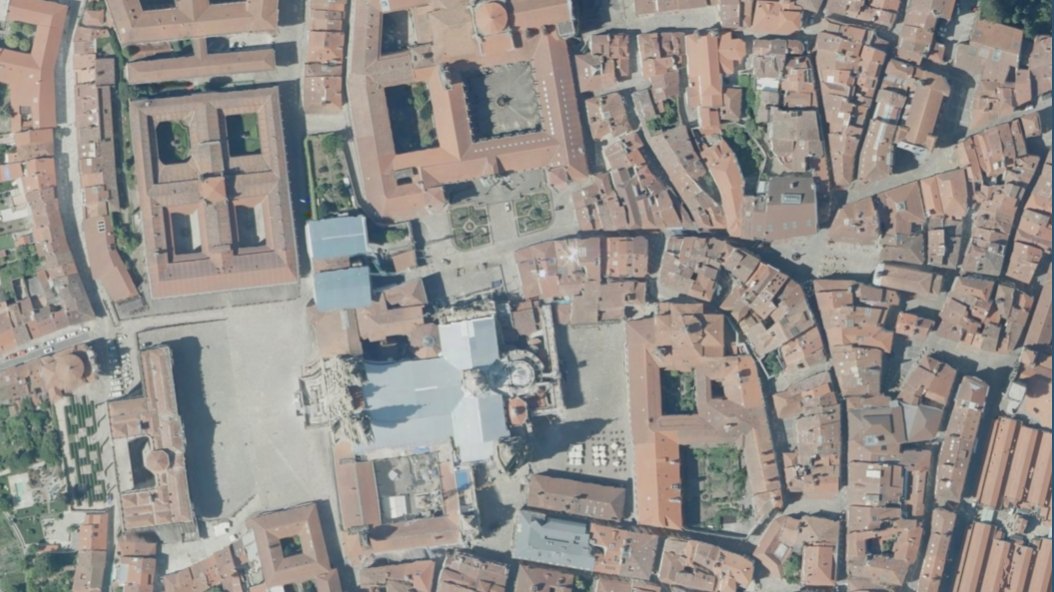
No mosaicking.
No stitching.
The true orthophoto comes straight from the adjusted dataset, with no mosaic to assemble and no seams to stitch: a versatile product for map production.
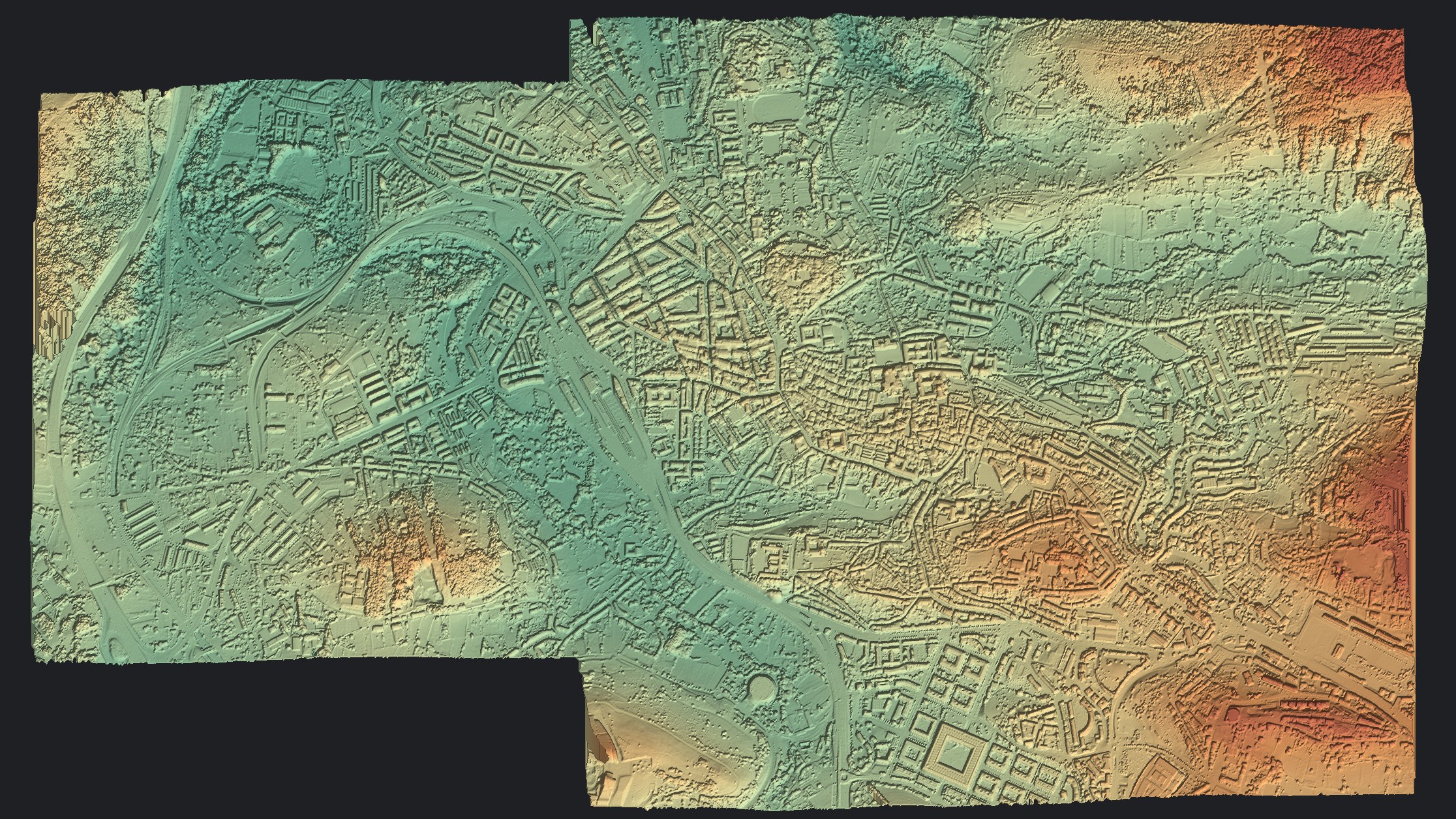
Point cloud and DSM
The DSM is derived from the point cloud.
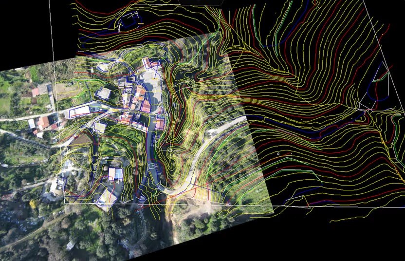
DTM and contour lines
Derived from the point cloud.
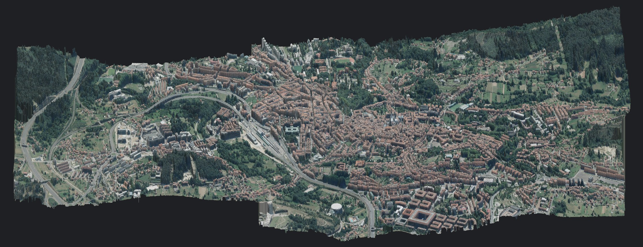
3D mesh model
Of the surveyed object, from conventional aerial photogrammetry, drone or terrestrial photographs.
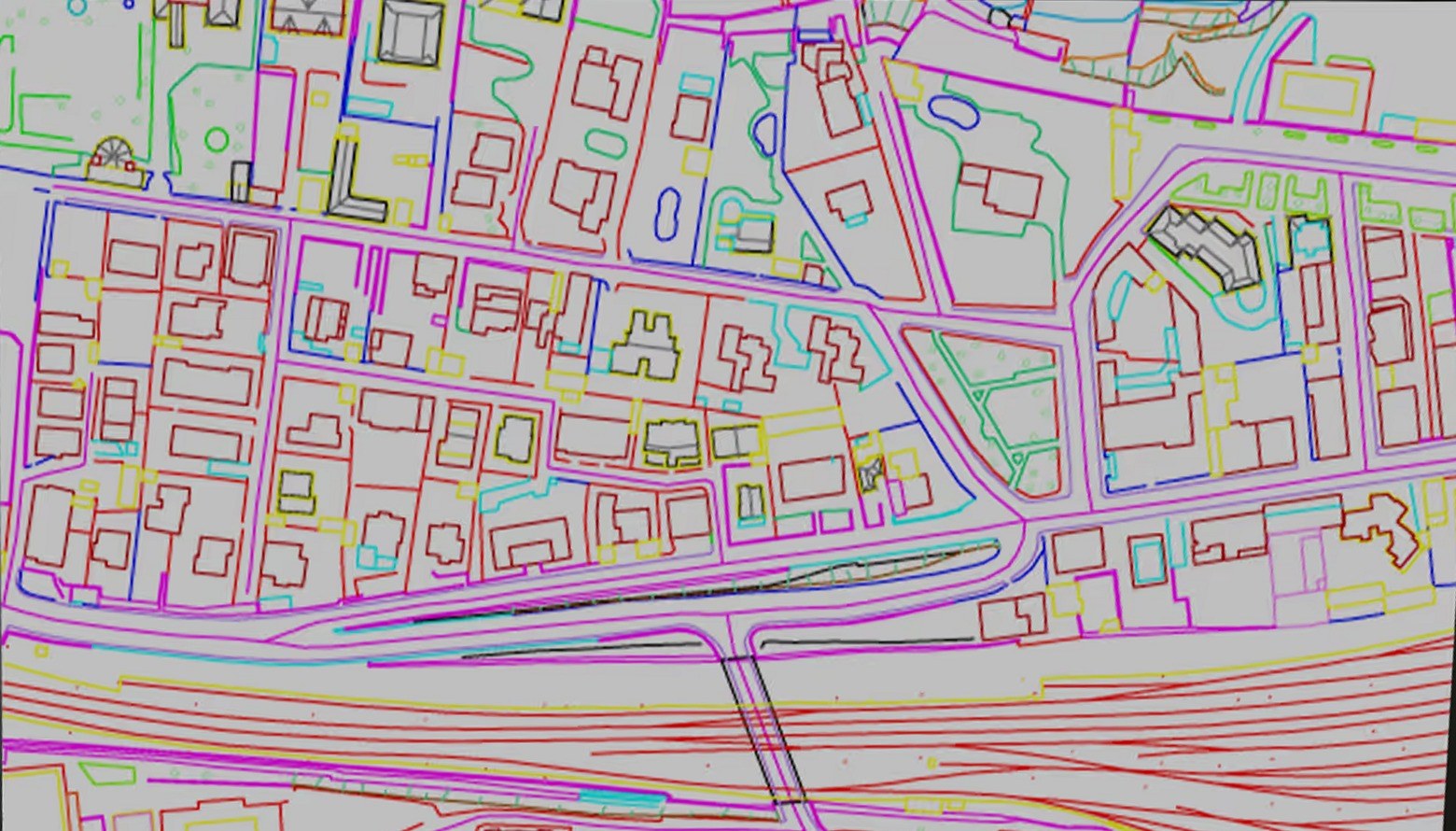
Stereo restitution
In the StereoCAD drawing environment, built for the most demanding stereo operators.
DSM and 3D mesh: Obra derivada de PNOA 2020 CC-BY 4.0 scne.es
For StereoCAD users
Everything you knew stays.
The rest is added.
Until now StereoCAD worked on datasets oriented by others. Now it recognises, analyses and adjusts the dataset your client gives you. Datasets already oriented by others still go straight to stereo, as before.
| Aspect | Until the previous version | From the October 2026 release |
|---|---|---|
| Input dataset | Already oriented by third parties | Supplied by the client as it is, recognised automatically |
| Orientation and adjustment | Outside the software | Inside: rigorous aerial triangulation or bundle adjustment with self-calibration |
| Outputs | Restitution and map databases | Point cloud, DSM, DTM, contour lines, 3D mesh, true orthophoto, plus restitution |
Stereo
Seen in depth, drawn where it is
Two overlapping photographs, seen one per eye, give back the relief of the ground. The floating mark rests on roofs, kerbs and terrain, and every vertex you draw has its true height.


The way photogrammetrists read it
The pair follows you across the block: when you move, the next pair is already there, with no jump in the image. Brightness and contrast are set for the whole block or for a single image.
- Beam-splitter mirror with two monitors
- Active shutter glasses
- Side-by-side and top-bottom
- 3D mouse and trackball
New with the October 2026 release · Stereo AI
Ask Stereo AI.
The assistant inside StereoCAD.
Press Ask Stereo AI in the menu bar and say what you want to get: Stereo AI knows the guide, reads the state of your project and its log, and answers with the steps — naming the windows and buttons you will see, and opening and filling the right window for you. The button that starts the work is always yours.
Ask it as you would ask an expert colleague: “I imported a flight with GNSS and six control points: how do I orient the block and check the error is under 5 cm?” · “Contour lines every metre only over the quarry: which steps?” · “I need an orthophoto and a DSM at 10 cm in UTM 33N: where do I start?”
Stereo AI uses AI credits, always shown in the status bar and topped up online from the program.
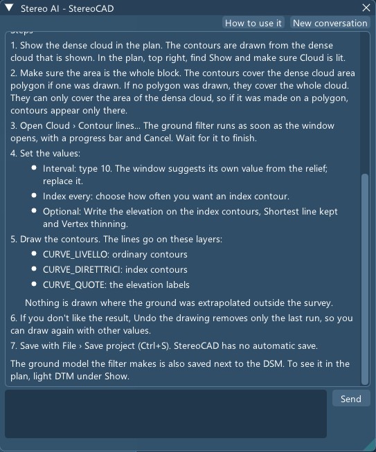
In stereo
Every vertex
at its height.
From the eave to the ridge, from the kerb to the manhole cover: every vertex drawn in stereo takes the height of the floating mark, and the drawing stays in 3D all the way to delivery.
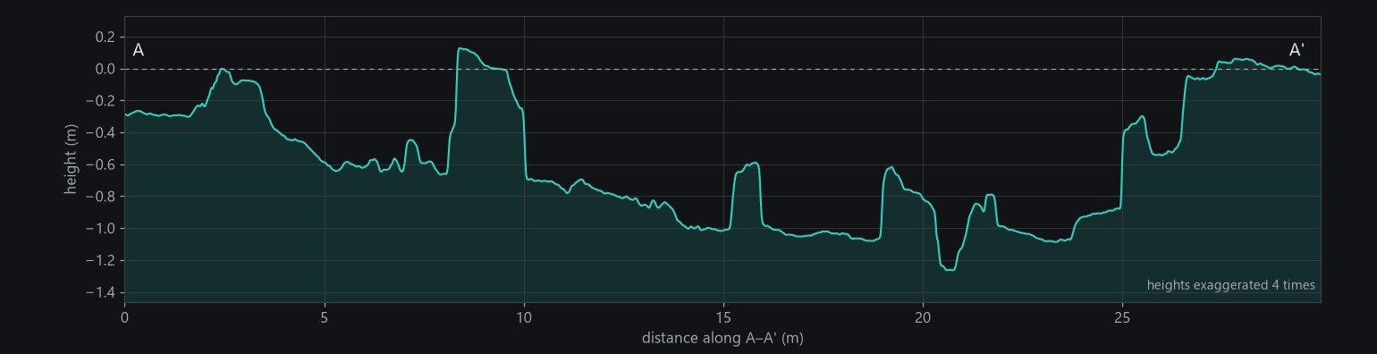
Sections come from the same heights. Here, a cut across an archaeological excavation: walls and trenches to the centimetre.
Mono
No stereo hardware?
Draw on the images.
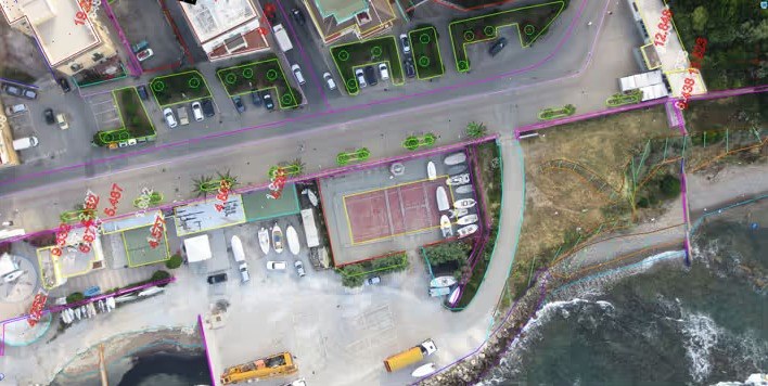
Without glasses or a stereo monitor, the mark follows the DSM or the dense cloud: you draw on the images with the right height, on the screen you already have.
CAD
A complete CAD,
fast and precise.
StereoCAD draws with its own native CAD engine, in world coordinates with real heights: every vertex digitised in stereo takes the 3D point of the floating mark. A real CAD, not a digitising window: the commands and aliases you already know, and the ones photogrammetric restitution needs.
- 100+commands at the command line
- 40+in the Modify menu alone
- 8object snaps, plus polar
- 115feature codes in the example library

- Drawing: points, lines, polylines, rectangles, circles, arcs, ellipses, splines and every kind of dimension.
- View: extents, window, previous, selection, and distances measured on the spot.
- Plan layers: orthophoto, DSM, dense cloud and drawing on or off with one click, and the 3D view.
- Stereo: the stereo output (beam-splitter mirror, active shutter glasses, passive 3D monitors) next to the CAD.
- Object snap: end, middle, centre, intersection, nearest, point, perpendicular, tangent, polar and XY only, at the height of the floating mark.
- Properties: layer, colour, linetype and lineweight of new objects and of the selection.
- Editing: erase, move, copy, rotate, scale, mirror, offset, trim, extend, fillet, stretch, break, join, explode, square, parallel, lengthen, densify, heights.
- Layers: on, lock, colour, linetype and entity count of every layer; feature codes create their own.
- Overview: the whole block, its strips and the stereo pair you are working on.
- Command line: every command by name, alias or Italian name, with its options and typed values (x,y and @dx,dy).
Stories from real data
Each story follows one dataset from the raw images to the result, step by step, from a pocket camera to a large-format aerial camera. Two are free benchmarks that anyone can download to check every number; the others are our own surveys.

A regional block, 70 gigapixels
357 frames of 196 megapixels, 267 GB, 109 km of plain: one project, from the whole block to stereo at the native 20 cm pixel.
Read the story →
Santiago de Compostela
Seven aerial images with their orientation: import, check, stereo, dense cloud, DSM and orthophoto.
Read the story →
Zeche Zollern, Dortmund
583 raw drone images: aerial triangulation, dense cloud, DSM and a 2 cm orthophoto.
Read the story →
A golf course under construction
161 pictures from a pocket camera, no GPS, fifteen ground points: measured to 2-3 cm.
Read the story →
An archaeological excavation
81 pictures from a pocket camera, no ground points: stereo, a sub-centimetre surface and a section.
Read the story →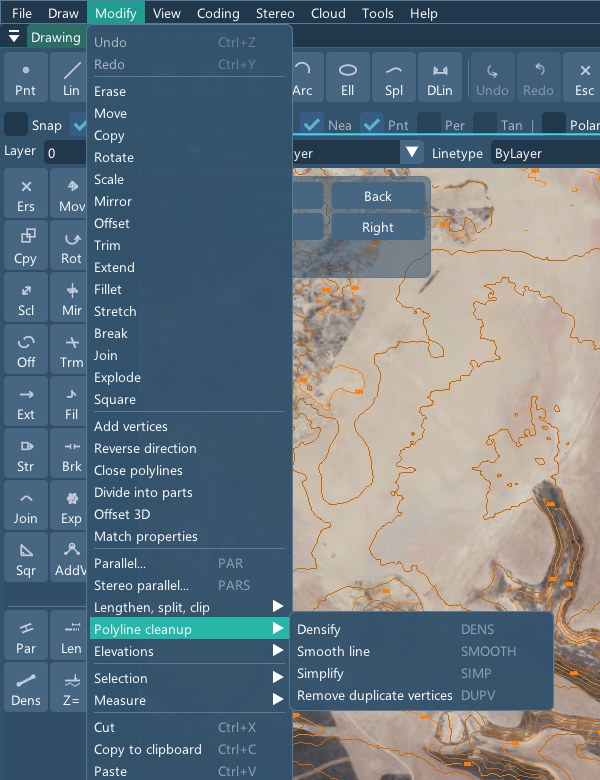
Editing
Every edit,
in three dimensions.
The Modify menu alone holds more than forty commands. Next to the classic CAD tools are those of restitution: parallel and parallel in stereo, polyline cleanup (densify, smooth, simplify, duplicate vertices) and heights (constant height, interpolate between the ends, level to the contour interval, drape on the terrain).
Codes and delivery
Each object on its layer,
with its data.
Feature codes and attributes put every object on its layer, with its symbol and its data, as your client's specification asks.
Delivery
In the formats
your client expects.
The drawing goes out in DXF and DWG, with the orthophotos placed in it, and to GIS as Shapefile or GeoPackage in 3D, with one field per attribute.
Contour lines
Contour lines
of the ground, not of the roofs.
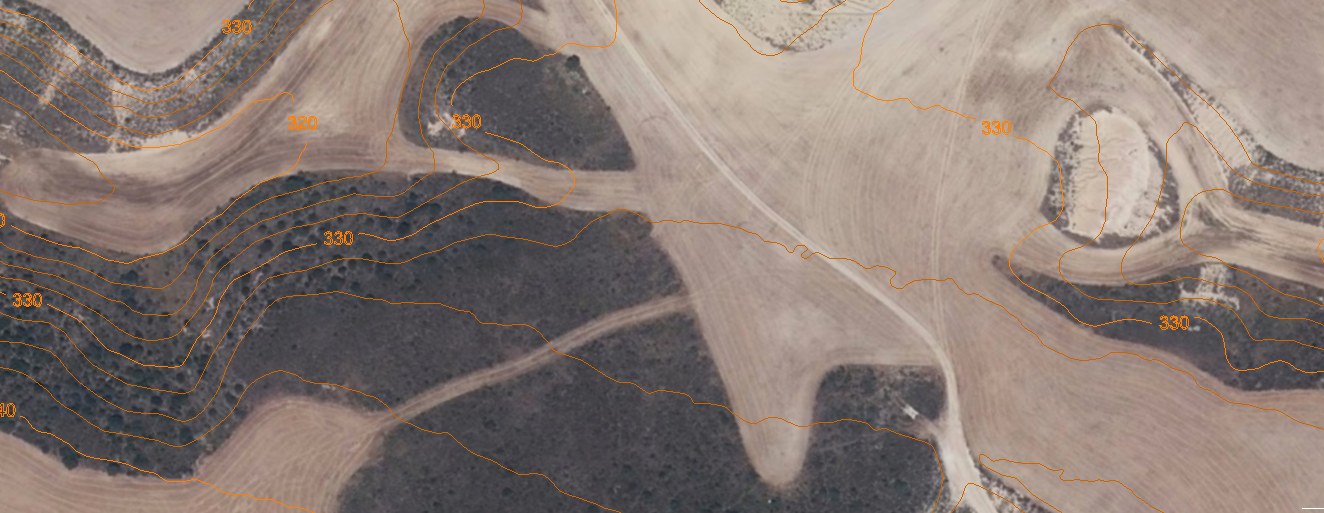
The ground is filtered from the dense cloud (roofs, trees and cars taken away) and the terrain is smoothed before the lines are traced, so the lines of one surface never cross. Ordinary and index lines on their layers, the elevation written in a gap of the index line, every line an editable CAD entity.
On two square kilometres of badlands in Navarre: 567 lines instead of 2,219, the escarpments where they were.

What you need
Computer
- Windows 10 or Windows 11, 64-bit
- A discrete OpenGL 3.3 graphics card; NVIDIA RTX with 8–16 GB recommended for the dense cloud
- 16 GB of memory minimum, 64 GB recommended; images and projects on an internal NVMe SSD
- An internet connection while the program is in use: the license is verified online
Stereo, optional
- A 3D polarised monitor with passive glasses as the second screen, or two monitors with a beam-splitter mirror
- A 3D mouse or a trackball beside the mouse, strongly recommended
StereoCAD is developed and distributed by MENCI Engineering srl.
Designed by dr. eng. Luca Menci, it builds on more than thirty years of stereo restitution software. It shares its CAD and its stereo with StereoCloud3D, which does for LiDAR point clouds what StereoCAD does for images.
Already a customer? Download the installer with your license key. USB key licenses only work on installations made before 1 October 2026; older versions are no longer available.
Request information
Tell us about your images and what you need: we answer within one working day, and arrange a demo on data like yours.
Or write to info@menci.com · WhatsApp +39 338 280 6914